Space exploration has undoubtedly occupied an important place in the interests of mankind over the last 50 years. Names like Challenger, Apollo or Columbia are not unfamiliar to anyone with access to radio or television who lived through the decades between the 1970s and 1990s. All these names are part of mankind's achievements in the 20th century during the heyday of space exploration.
Both manned and cargo spaceflight have been made possible by a long chain of technological and scientific advances that have nurtured space agencies from the early years of the space race to its later years. Engineers and scientists from all over the world have put their efforts into improving both the reliability and safety of the mission, as well as optimising the equipment to make these journeys at the lowest possible cost, leading them to explore the most innovative and interesting technologies, among them solidrocket propulsion.
Solid fuel rockets are used as space shuttle boosters during the first two minutes of flight. They consist mainly of a casing, an insulation layer, a nozzle, the propellant charge (solid fuel) and an igniter to start the ignition of the system. The major novelty of this propulsion system lies precisely in the type of fuel used (solid fuel), which provides many advantages over liquid fuel propulsion systems.
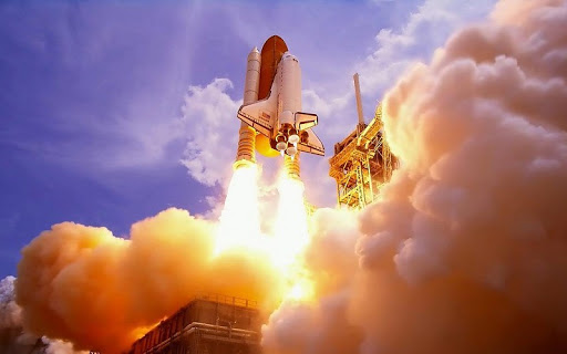
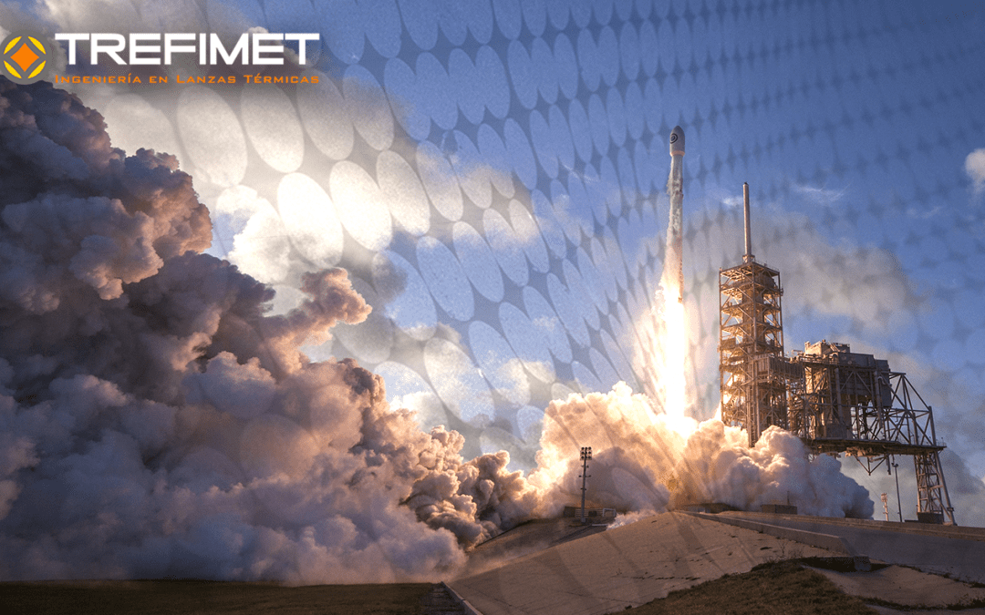
Figure 1. Launch of the Space Shuttle Discovery
One of the most important points is the high density of these fuels compared to other liquid fuels, being able to store a greater amount of "energy" within the same geometry. The fact that the fuel is in a solid state and is noticeably less volatile than liquid fuels makes it safer and easier to store, much simpler to handle and reduces both construction and disposal costs.

The "propellant" material is a mixture of an oxidising agent, a material to be oxidised and a binder. Generally, ammonium perchlorate (NH4ClO4) is used as oxidising agent, atomised aluminium as fuel (Al) and HTPB (polybutadiene with hydroxyl radicals) as binder (CxHyOz). The reaction between these compounds generates different gases, which inside the combustion chamber can reach temperatures of up to 3400 [K] and 2200 [K] when expelled through the nozzle (given the expansion that occurs).
The nozzle design is what allows the outgassing, which in turn also regulates the burn rate of the solid fuel, encapsulated in the main structure. These can escape through the nozzle at speeds of up to 1500 m/s, generating the thrust needed to accelerate, for example, a space shuttle in conjunction with the two booster rockets that commonly make up the typical launch configuration. This assembly weighs approximately 2000 tonnes.
The thrust behaviour during acceleration depends on the cross-section of the fuel distribution in the rocket. Since combustion occurs in the central area of the rocket and the thrust is directly dependent on the burn area of the rocket, the geometry of the central "bore" determines the type of flight the propellant can provide. For example, if the geometry consists of a circle (tubular, see figure 3), the type of thrust will be progressive, since the burn area will increase as the fuel burns, so the thrust will increase over time, whereas in a multifin (No. 4 in figure 3) the burn area is initially larger, but as the burn radius increases the area does not increase to any great extent, and the thrust remains constant for the majority of the flight.

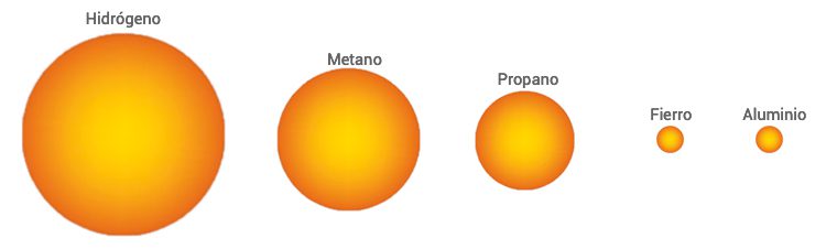
The oxidation of solid fuels is highly energetic, for example, if taken on a comparative scale for known fuels, the oxidation of Aluminium (Al) delivers 83781 MJ/m3, while propane generates 99 MJ/m3, generating 846 times less energy per cubic metre of fuel. Figure 4 shows the proportional differences between solid fuels (Al and Fe) and gaseous fuels (hydrogen, methane and propane).
In addition to the characteristic of high calorific value per unit volume of solid fuels, it is important to know that the reactions occur in different states (solid, liquid or gaseous) depending on the material, for example, the oxidation of aluminium is in the liquid state (> 2000°C) and that of iron is in the solid state (870°C). This allows different types of applications to be defined, such as thermal lances that are used to cut or perforate any existing material by fusion.
Using the energy of a solid that reacts in this state, as is the case of iron, has a very relevant application in casting processes, since in order to pierce the plugs that hold the molten material (liquid) inside the furnace, materials with high resistance to heat energy are required. To pierce these plugs, the industry has been developing different technologies for more than 130 years, but to date no product has been found that can effectively open 100% of these plugs other than thermal lances. Therefore, in parallel to these developments, research and work continues on the reaction of Fe with O2 to perfect thermal lances, which are the only tool that can pierce 100% of the corks.
From all this it could be said that spacecraft take advantage of the transformation of the high thermal energy of solid fuels into high kinetic energy which results in high thrust, while in the case of foundries the high thermal energy in the solid state of iron is used to concentrate it in a precise point and melt the plug. In both situations, the expected result would not be achieved with conventional fuels.
Interestingly, the optimisation of thermal lances involves the development of configurations very similar to those of space rocket nozzles, as shown in Figure 5.